...unless I'm mistaken of course, but from what I've looked, no one has (yet) built a guitar amp based on the STM32 ARM microcontrollers. So, this one's the first!
I've been working on my DIY guitar amp for a couple of years, starting as early as 2012 or so I recall, with the cabinet.
While I could have gotten a good modeling amp (Line6, VOX, et al) I think they are way over the top for what I want. Too many effects, in the end, you fiddle more with the amp than with the guitar. But an all analog design while nice, can be modified only on hardware, and those are costly and time consuming iterations. No problem with that, but you also want to have decent results from time to time. The idea came to me then, 2011 actually, why not build a very simple input stage with some gain, pass it onto a microcontroller via a ADC, add some effects, and take the output out via DAC / Amp combination?
 |
| The first effects processor board |
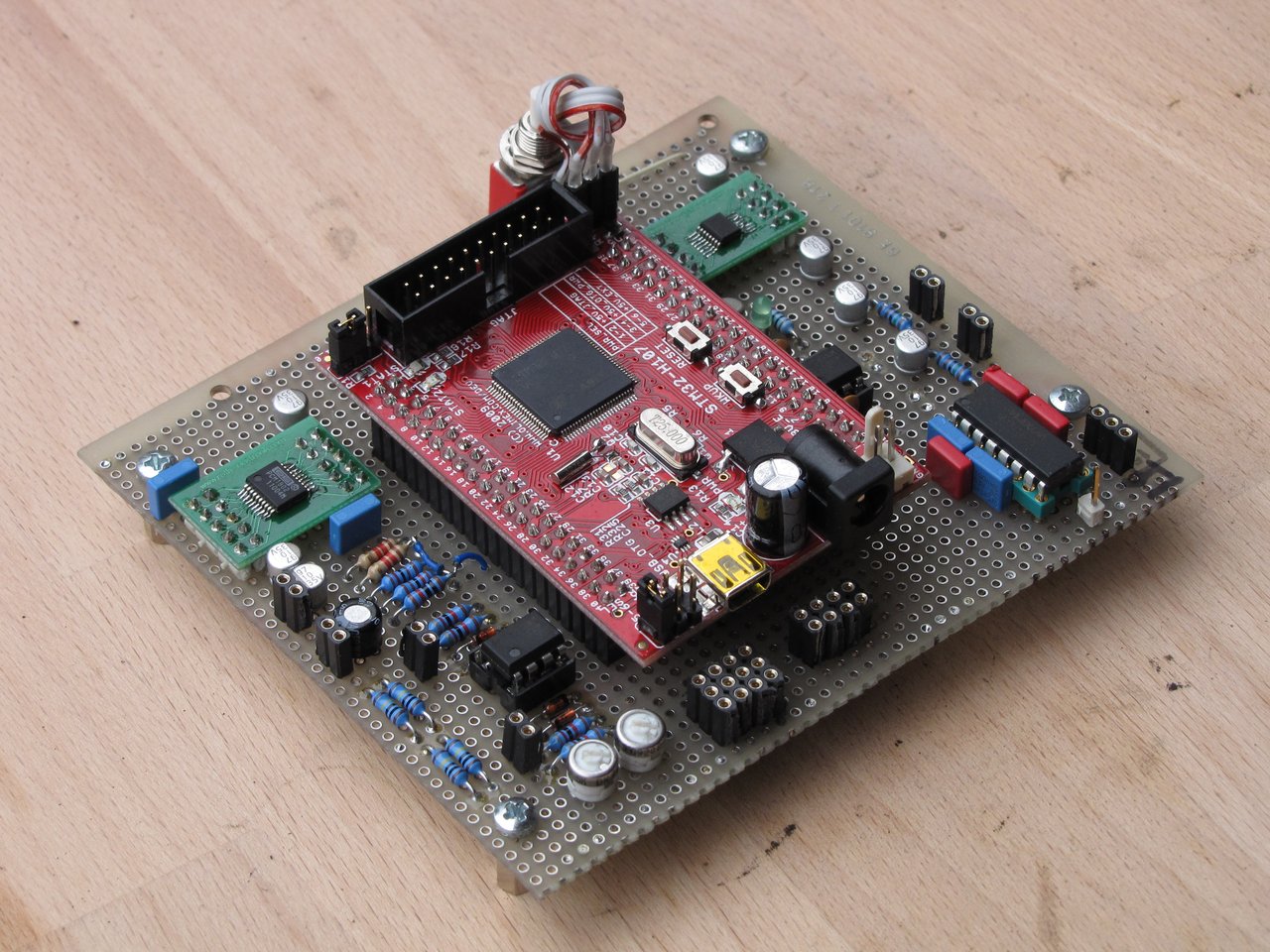
Surely the first tests worked quite well! What you see on top is the first try, around March/April 2012. The top board is an Olimex STM32-H107 board (thanks to Uwe for lending me that... sorry Uwe, now it's in Australia with me... let me know if you want it back!), mounted on a board I built with an ADC (left), a DAC (roght) and a serial interface for programming (bottom right).
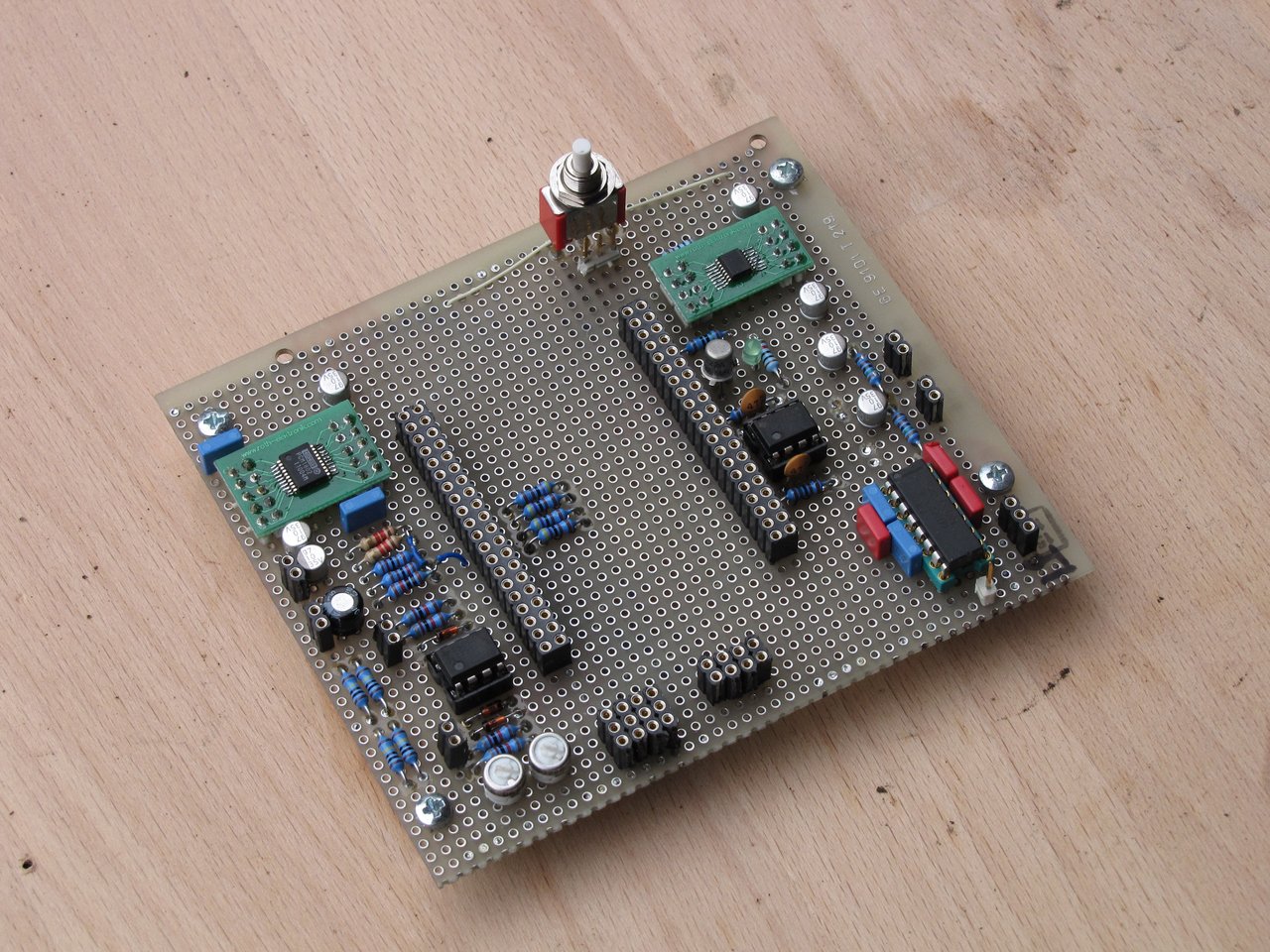
It looks a bit untidy, but as a first attempt I got it working nice. At that stage I decided to build a cabinet/head for the amp as well.
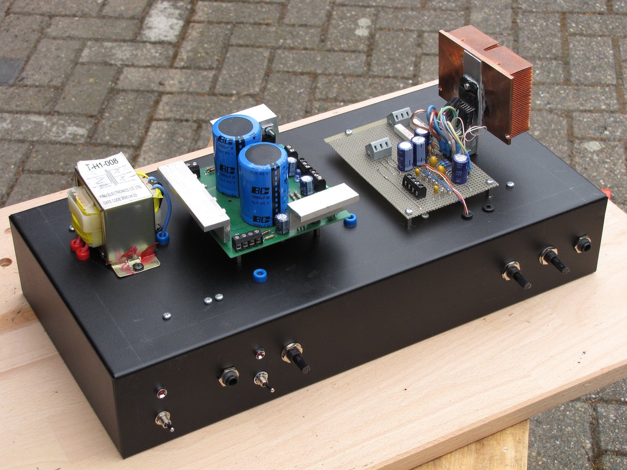 |
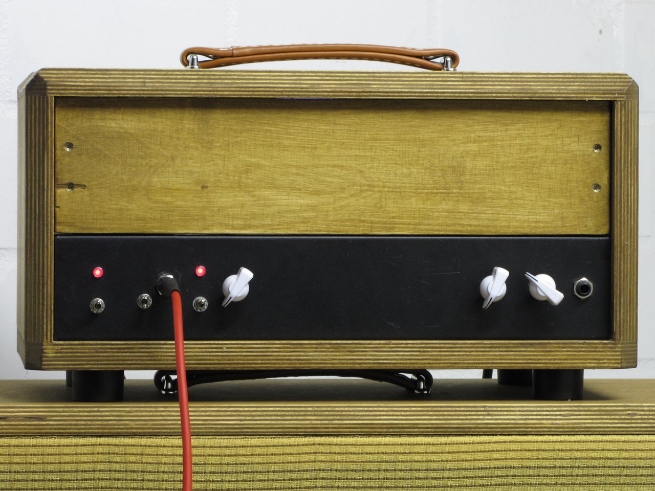
| The first amplifier build |
 |
| Early stages |
But... I'm getting a bit ahead of myself. Why don't I start and build the different components from input to output? That would make more sense.
I'm going to skip the power supply, as there are countless good designs, and this amp uses two (as in 2) standard textbook transformer / diode bridge / capacitor combinations. First is a 150W transformer to generate +/- 28V unregulated for the power amp. Second is a 10W transformer that generates +/- 12V unregulated for the analog preamp and the µC board. Enough for me, works well.
Let's have a look at how the amp is built.
Overview
 |
| The current design |
In a nutshell, the analog pre provides an analog amplification stage before going into the ADC, with a soft limiter so as not to exceed 2.5V peak at any time.
The amplified analog signal is fed into the µC Test board (details here). The µC adds a bit of 2nd harmonics to the input signal, a switch selects between clean and distorted channel (more distortion is added at this point), and all of it goes into a very simple yet strangely effective reverb. Before the signal is put out through the DAC, a software limiter makes sure that we don't have digital overflow, otherwise the sound sucks big time.
The (at this point) heavily modified signal goes into the analog power amp, which offers variable gain and a main volume regulator. It's also designed with a soft limiting function in mind, in case the gain is at maximum and the signal from the DAC is too high.
The output from the power amp is fed into a 2x12 custom made speaker cabinet, with two Celestion Greenbacks.
The Analog Preamplifier
The analog pre is pretty simple.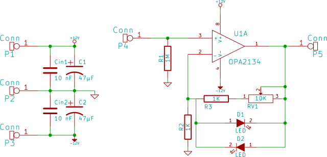 |
| Analog preamplifier schematics |
Based on a OPA2134 (only one half is used) it takes the signal from the guitar and amplifies up to 20 dB, controllable by a gain pot. However, should the voltage go over around 2V max, the amp starts limiting the input, so as not to have a hard limit on the ADC input. It also gives the guitar a nice distorted sound if you crank it up, even before adding extra effects. This is done by green LED's in parallel with the feedback resistors. The output voltage would then rarely, if at all exceed, 2.5V peak.
Note to self: read the data sheet for the ADC. All this time I was under the wrong assumption that while the analog supply voltage was 5V, the input voltage swing would be +/- 2.5V. But nooooo.... The datasheet for the PCM1802 states, maximum input voltage swing 0.6xVcc, +/- 1.5V. Bugger! So I had to modify the circuit a bit and add a resistor between the analog signal and the ADC to scale the input voltage from 2.5V peak to 1.5V peak.
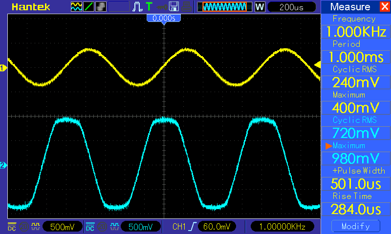
Back to the preamp. I'm using a 240mV RMS 1 KHz input signal into the amp, which is more or less the output level on an electric guitar (it varies, but it's a good approximation).
With the volume in the lowest position, the original input signal (yellow) is attenuated by a factor 2.4 (-7.6 dB, blue signal).
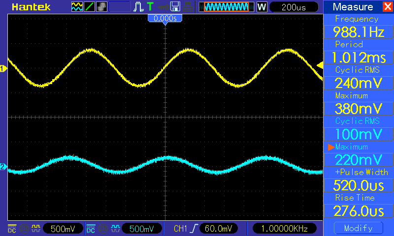 |
| Yellow: Input Signal, Blue: Output Signal |
At around 8 - 9 o'clock pot position, it's the same signal.
 |
| Yellow: Input Signal, Blue: Output Signal |
At 12 o'clock pot position, it gets interesting! The input is amplified by a factor 2.7 (8.6 dB). Note there is a small flatness to the output signal on the peaks.
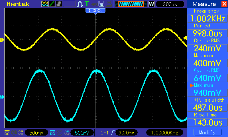 |
| Yellow: Input Signal, Blue: Output Signal |
2'clock, even more compressed, without being a flat top.
 |
| Yellow: Input Signal, Blue: Output Signal |
Pot at the end position, the peak voltage hasn't changed much compared to before, and the total gain is about 3.1 (5 dB).
 |
| Yellow: Input Signal, Blue: Output Signal |
But the most important part of all this, we're well within input range to the ADC, so there's no hard signal saturation at the input.
The effects processor
This is where it gets interesting. Best to start with an overview of the complete signal path inside the µC and then complement each segment with its characteristics.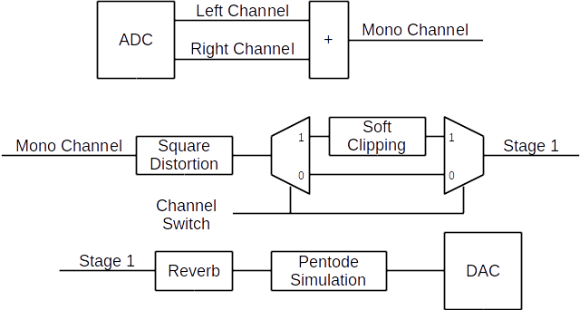 |
| Overview Digital Effects Processor |
The ADC works at 24 bit / 48 KHz, all calculations are made using 64 bit signed integer logic and are scaled during the process accordingly to remain always within 24 bits. Not to complicate things too much in here, but to ease the calculations, I scaled the integers so that the full scale range is between -1 and 1. I'm not going into more detail with that, and I'll show a representation of what each module does in an analog way.
Square distortion
I remember reading a few years ago that a tube produces 2nd harmonics distortion at certain bias and amplification levels. 2nd harmonics can be recreated (on a pure sine wave) by squaring the signal and adding it to the original signal. The input signal is then modified as shown below.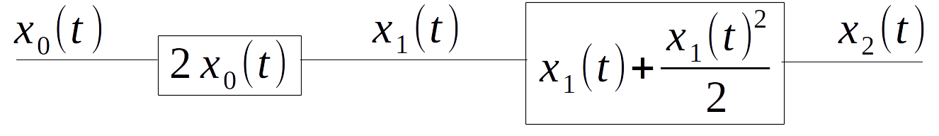 |
| Square Distortion Function |
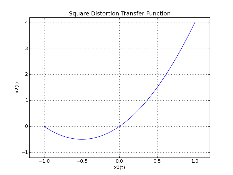
The transfer curve of the above function looks like:
Soft Clipping
Credit where credit is due. This was taken out of the book "DAFX: Digital Audio Effects" by Udo Zölzer, also described as soft clipping.Whenever this effect is selected by a switch connected to the microcontroller board, the signal is modfied by the function below.
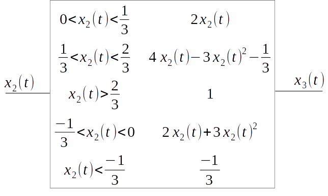 |
| Soft Clipping Function |
The transfer curve of the above function looks like:

The Invisible Filter
The square distortion and the soft clip transfer function add different levels of DC component to the signal. That on one hand alters the sound, on the other hand, in some cases prevents that we take advantage of the full range of our functions. In order to avoid a piling up of DC component further down the signal path, a high pass filter is introduced at Stage 1, just before the Reverb component. I'll not go into details, but it's a very simple IIR 2 zeros, 2 poles filter with a very low cut off frequency.Reverb
This is a tricky one to get right! I think I got halfway there anyway, and it does an OK job. I based the design on some parameters taken from James Moorer's paper "About This Reverberation Business", I think it's from 1979, but I'm not sure. In this paper Moorer explains the approaches for digital reverberation at the time, some improvements, and finally gives some numbers that represent the initial impulse response of a sound hall.I took those values, but given the memory limitations of the controller, I didn't implement all six or so delay lines, but used a different approach. I'm also not showing any transfer function curves, rather the implementation I used. It's a very subjective and difficult part of the amp, more that one would think!, however, you'll hear the effect on the sound bites at the end of the article.
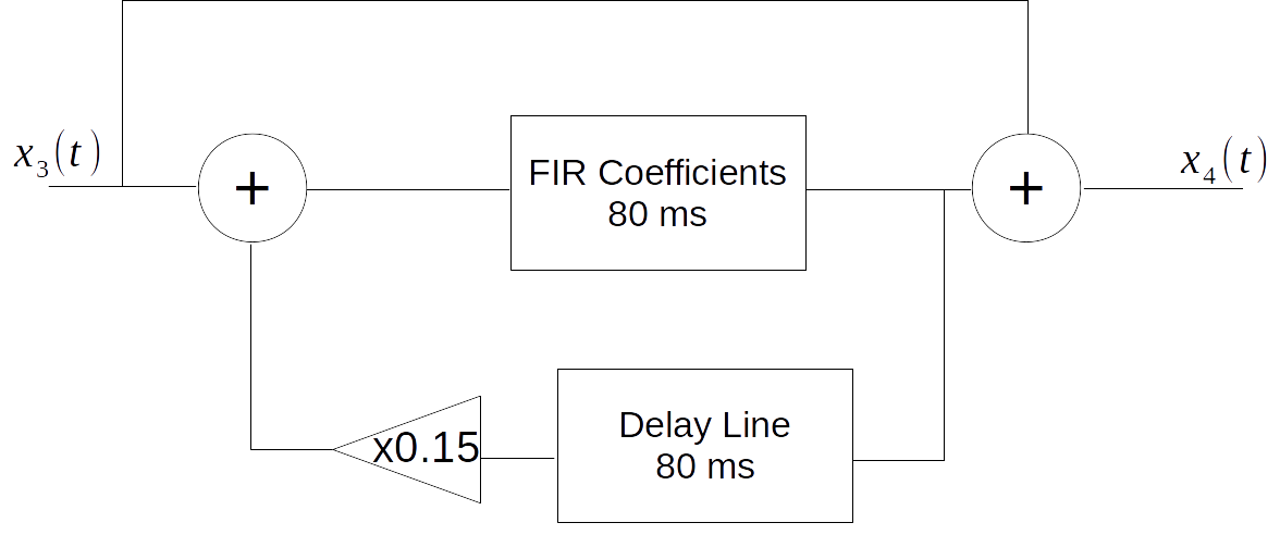 |
| Reverb Unit Structure |
The FIR coefficient values can be looked up in Moorer's paper.
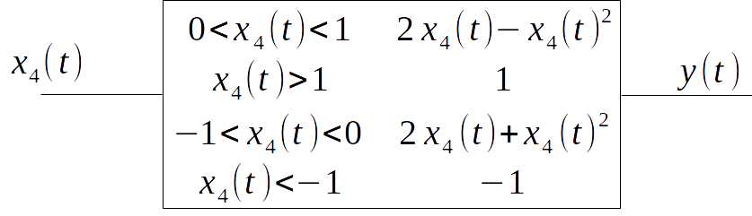
The Pentode
Ok,
I called it the pentode... can't really remember why. It's the last
stage before the output to the DAC. It prevents the digital signal,
however high, from overflowing (that creates really nasty artifacts on
the analog signal), and it gives a softer clipping rather than a hard
limit. Bear in mind though, if the input signal is very high, hard clipping is unavoidable.
The pentode is simulated with:
 |
| Pentode Function |
And the transfer curve looks like:

The power amplifier
This is the last stage before going into some practical examples. The power amplifier is based on an LM3886 chip board, single channel. Basic design, taken from the datasheet. At maximum gain it delivers 25W into 8 or 50W into 4 (I'm usually driving 4 on my cabinet). It features variable gain, 18dB to 26dB (8x to 20x), and the overall volume is controlled by a pot between the effects processor output (the DAC output) and the power amp input. It also makes use of the LM3886's mute switch, controlled by an opto coupler, to avoid pops when the amp starts. The mute control is switched off after around 500 ms after the complete amp is started.
 |
| Power Amplifier Schematics |
Final thoughts before some images and sound clips
I hope I finished. I really do! I've been tweaking and changing and trying, especially on the digital side of things, until I found a couple of sounds I'm happy with. Is the sound "authentic"? Will the amp hold its place against serious tube contenders? Honestly, I doubt it very much. And yet, I don't mind at all.
In the end, the goals of the projects were achieved:
- 2 channels, clean and dirty
- An analog pre amp section
- A simple digital reverb implementation
- It shall be loud!
- It shall be made on a Cortex M3, used as a DSP
- It shall be simple! As much as I love devices like Line6 or Vox digital amps, I got lost using them! I want a few knobs, and the rest is up to the player.
On purpose, I completely neglected the effects of non linear operations sampling at 48 Khz. These non linear operations might or might not introduce some artifacts like aliasing into the signal, but given the complexity of removing those, I preferred to ignore them. Mea culpa.
At this point, the way it's working now, all the processing is done between samples. It might improve performance if I took a batch of samples for processing, but at the cost of some delay (not much, true). Given that the amp still works this way, I have no intention of changing that. I might measure how much time it takes for an effects processing cycle to complete (with and without soft clipping), but at the moment the M3 is managing quite well.
Finally, it was lots of fun, it took way more time than expected, and I suspect I'm not ready yet... what about a compressor, some bass and treble controls, etc, etc...? On a future build, I know already what pitfalls to avoid, which components work well, what processor I should use, and how to wire all together.
If you made it this far, thanks! Now let's look at some pics and see if I record some bits. Don't judge me on the playing (it's rubbish), but on how the guitar amp sounds!
Images
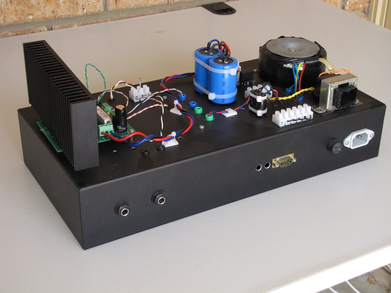
On the left, a 120W 20V transformer (toroidal) and a 10W 6V transformer. +/- 9V and +/- 28V are generated from the power supply which occupies the left half of the case. The 9V supply powers the µC board and the pre amplifier, and the 28V supply powers the power amp. On the right, the LM3886 amp board.
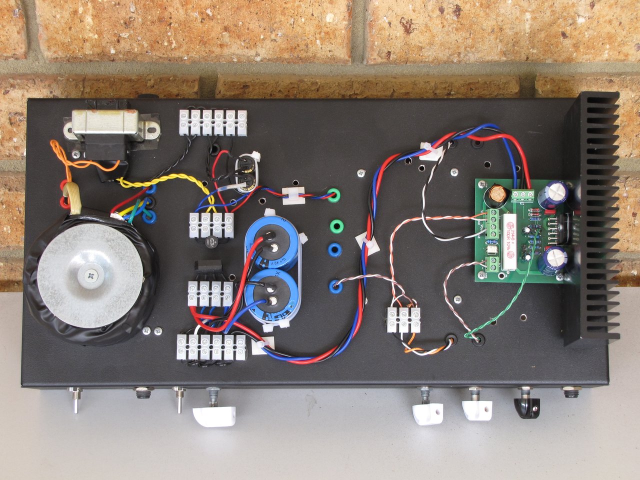 |
| Top View |
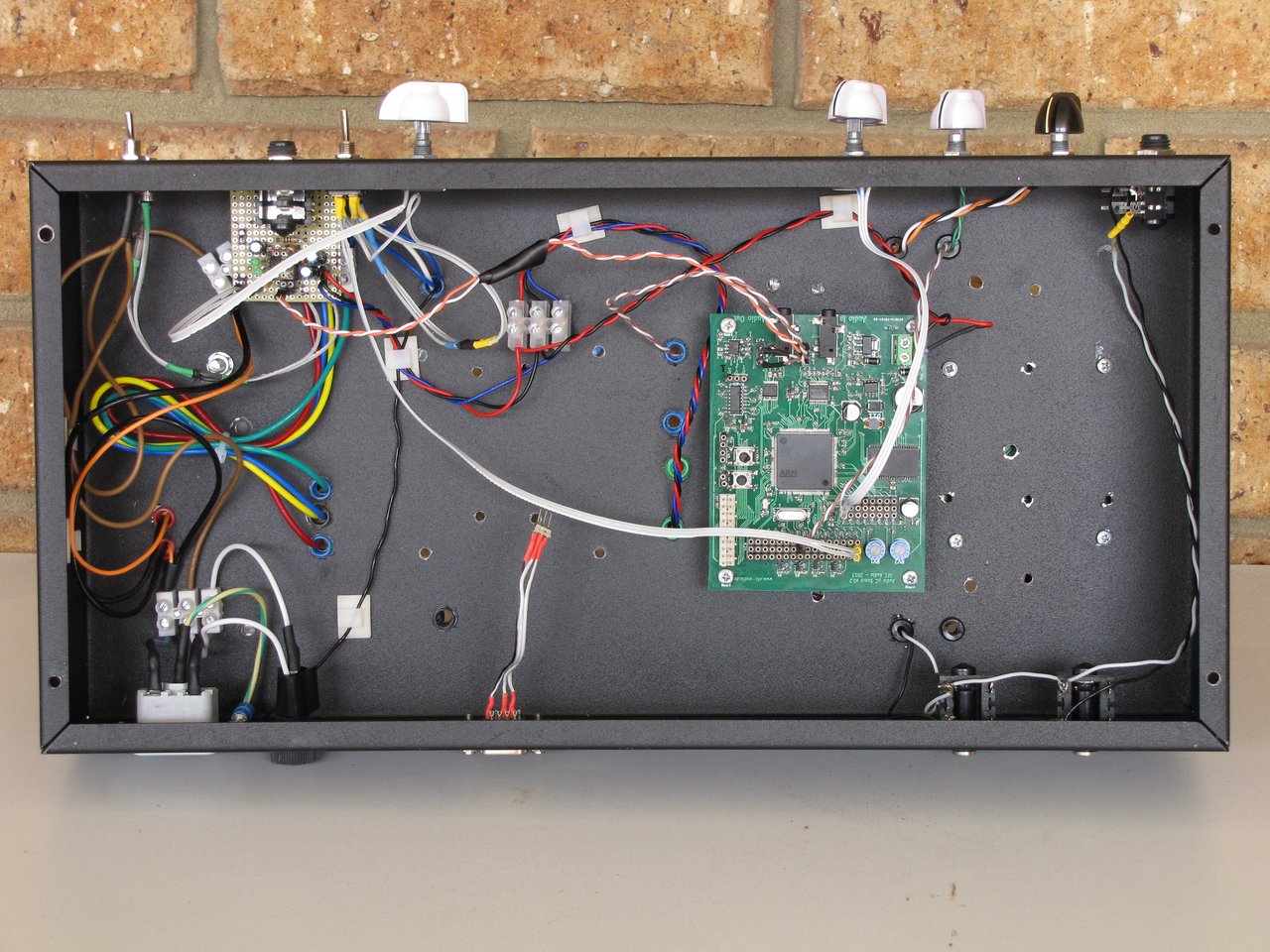 |
| Inside View |
 |
| Front View |
 |
| Back View |
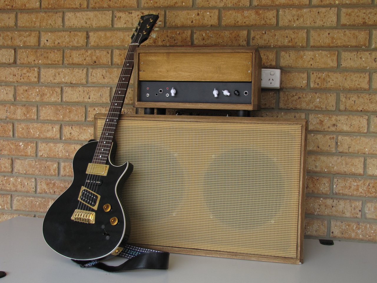 |
| The Complete Rig |
Sound Clips
Here's a few examples how the amp sounds.
(Soft clipping on, reverb at lowest, preamp at 12 o'clock)
(Preamp on lowest, highest reverb, no soft clipping)
No comments:
Post a Comment
Note: only a member of this blog may post a comment.